- 您现在的位置:买卖IC网 > Sheet目录307 > ADM8843ACPZ-REEL7 (Analog Devices Inc)IC LED DRVR WHITE BCKLGT 16LFCSP
ADM8843
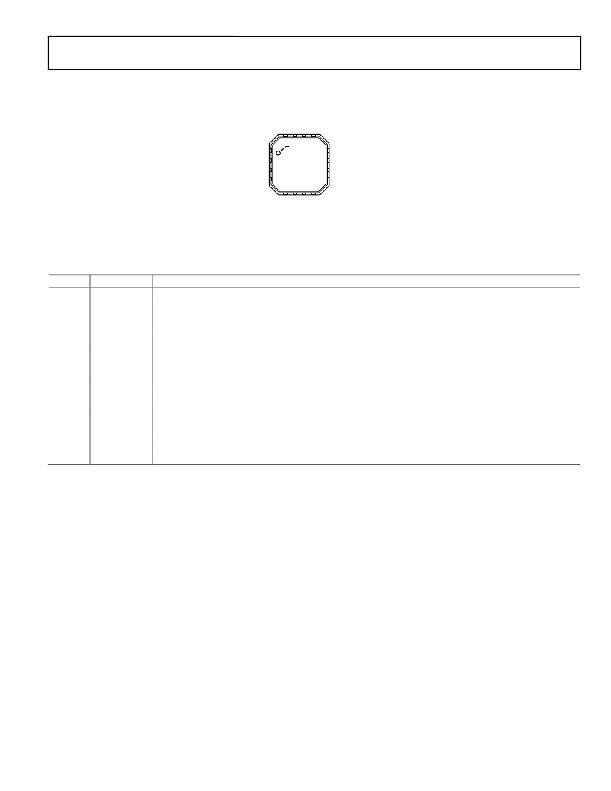
PIN CONFIGURATION AND FUNCTION DESCRIPTIONS
PIN 1
V OUT 1
C2+ 2
I SET 3
GND 4
INDICATOR
ADM8843
TOP VIEW
(Not to Scale)
12 CTRL2
11 C2–
10 GND
9 GND
NOTES
1. CONNECT THE EXPOSED PADDLE TO GND.
Figure 2. Pin Configuration
Table 3. Pin Function Descriptions
Pin No.
1
2
3
4, 9, 10
5 to 8
11
12
13
14
15
16
–
Mnemonic
V OUT
C2+
I SET
GND
FB1 to FB4
C2?
CTRL2
CTRL1
C1?
V CC
C1+
EP
Description
Charge Pump Output. A 2.2 μF capacitor to ground is required on this pin. Connect V OUT to the anodes of all the LEDs.
Flying Capacitor 2 Positive Connection.
Bias Current Set Input. The current flowing through the R SET resistor, I SET , is gained up by 120 to provide the I LED
current. Connect a resistor, R SET , to GND to set the bias current as V SET /R SET . Note that V SET = 1.18 V.
Device Ground Pins.
LED1 to LED4 Cathode Connection and Charge Pump Feedback. The current flowing in these LEDs is 120 times
the current flowing through R SET , I SET . When using fewer than four LEDs, this pin can be left unconnected or
connected to GND.
Flying Capacitor 2 Negative Connection.
Digital Input. 3 V CMOS Logic. Used with CTRL1 to control the shutdown operation of the main and sub LEDs.
Digital Input. 3 V CMOS Logic. Used with CTRL2 to control the shutdown operation of the main and sub LEDs.
Flying Capacitor 1 Negative Connection.
Positive Supply Voltage Input. Connect this pin to a 2.6 V to 5.5 V supply with a 4.7 μF decoupling capacitor.
Flying Capacitor 1 Positive Connection.
Expose Paddle. Connect the exposed paddle to GND.
Rev. C | Page 5 of 16
发布紧急采购,3分钟左右您将得到回复。
相关PDF资料
ADP1653ACPZ-R7
IC LED DRVR PHOTO FLASH 16-LFCSP
ADP1712-EVALZ
BOARD EVALUATION ADP1712
ADP1720-EVALZ
BOARD EVAL FOR ADP1720-ADJ
ADP2140CPZ-REDYKIT
REDYKIT 2 BOARDS ADP2140ACPZ
ADP3110AKRZ-RL
IC MOSFET DRIVER DUAL 12V 8SOIC
ADP3120AJCPZ-RL
IC MOSFET DRIVER DUAL 12V 8-DFN
ADP3121JRZ-RL
IC MOSFET DRIVER DUAL 12V 8SOIC
ADP3415LRMZ-REEL
IC MOSFET DVR DUAL BOOTST 10MSOP
相关代理商/技术参数
ADM8843ACUZ-REEL7
制造商:Analog Devices 功能描述:
ADM8843EB-EVALZ
功能描述:BOARD EVAL ADM8843 RoHS:是 类别:编程器,开发系统 >> 评估板 - LED 驱动器 系列:- 标准包装:1 系列:PowerWise® 电流 - 输出 / 通道:20mA 输出及类型:1,非隔离 输出电压:17V 特点:可调光 输入电压:2.7 ~ 5.5 V 已供物品:板 已用 IC / 零件:LM3508 相关产品:LM3508TLX-ND - IC LED DRVR WHT BCKLGT 9USMDLM3508TLDKR-ND - IC LED DRVR WHT BCKLGT 9MICROSMDLM3508TLCT-ND - IC LED DRVR WHT BCKLGT 9MICROSMDLM3508TLTR-ND - IC LED DRVR WHT BCKLGT 9MICROSMD
ADM8845
制造商:AD 制造商全称:Analog Devices 功能描述:Charge Pump Driver for LCD White LED Backlights
ADM8845ACP
制造商:Analog Devices 功能描述:CHG PUMP STPUP 30MA 16LFCSP - Bulk
ADM8845ACP-REEL
制造商:Analog Devices 功能描述:Charge Pump STPUP 30mA 16-Pin LFCSP EP T/R
ADM8845ACP-REEL7
制造商:Analog Devices 功能描述:Charge Pump STPUP 30mA 16-Pin LFCSP EP T/R
ADM8845ACPZ
制造商:AD 制造商全称:Analog Devices 功能描述:Charge Pump Driver for LCD White LED Backlights
ADM8845ACPZ-REEL
功能描述:IC LED DRVR WHITE BCKLGT 16LFCSP RoHS:是 类别:集成电路 (IC) >> PMIC - LED 驱动器 系列:- 标准包装:6,000 系列:- 恒定电流:- 恒定电压:- 拓扑:开路漏极,PWM 输出数:4 内部驱动器:是 类型 - 主要:LED 闪烁器 类型 - 次要:- 频率:400kHz 电源电压:2.3 V ~ 5.5 V 输出电压:- 安装类型:表面贴装 封装/外壳:8-VFDFN 裸露焊盘 供应商设备封装:8-HVSON 包装:带卷 (TR) 工作温度:-40°C ~ 85°C 其它名称:935286881118PCA9553TK/02-TPCA9553TK/02-T-ND
